Skip to content Skip to sidebar Skip to footer

iso 15614 1 pdf free download

Introduction

The long-awaited revision of ISO 15614 Part 1, the ISO standard for the qualification of arc and gas welding procedures for steels and Nickel alloys, was completed in the first half of 2017. The new version of the standard was published during June of the same year as ISO 15614-1:2017 and adopted by BSI as BS EN ISO 15614-1:2017. This superseded BS EN ISO 15614‑1:2004+A2:2012, which was withdrawn.

ad-generic-300x250

Click here to see our latest technical engineering podcasts on YouTube.

The 2017 version of the standard is the result of an extensive and lengthy revision process completed by the ISO /TC 44/SC 10 subcommittee and differs significantly from the previous version in format, with some major changes in technical   content. This article presents the most significant differences between the 2017 and the previous version of the standards, explains the rationale behind the changes and provides practical guidance on how to deal with them.

Questions on the application of clauses of ISO 15614-1 that are not described here, as well as on other welding-related standards, can be submitted via email  contactus@twi.co.uk.

DISCLAIMER - TWI is not authorised to give official interpretations of BS EN ISO standards. The views and opinions expressed in this article are those of the authors and do not reflect the official policy or position of ISO, CEN or BSI. This article is not to be taken as a substitute for the standard, which must be consulted where its application is required. No liability rests with TWI for any damages arising from the content of this article.

New: welding procedure test levels

The main change is that ISO 15614-1:2017 includes two levels of welding procedure tests, designated by levels 1 and 2. Level 1 is based on requirements of Section IX of the ASME Boiler and Pressure Vessel Code (ASME IX) and Level 2 is based on the previous issues of ISO 15614-1.

The introduction to the standard explains that this approach was introduced "in order to permit application to a wide range of welded fabrication". In Level 2, the extent of testing is greater and the ranges of qualification are more restrictive than in Level 1. Hence, procedure tests carried out to Level 2 automatically qualify for Level 1 requirements, but not vice-versa. It should also be noted that when no level is specified in a contract or application standard, the requirements for Level 2 apply.

In addition, in recent years, various industry sectors and standard development organisations have been pushing towards harmonisation and convergence between international standards, including those for welding qualifications. At the start of the revision process, the relevant ISO subcommittee carried out a comparison between corresponding requirements in ISO 15614-1 and ASME IX to evaluate the possibility to develop a 'one-size-fits-all' standard. This exercise showed that the differences were such that these two standards could not be merged into one, hence the decision to include a two-level approach.

As explained in the UK National Foreword to BS EN ISO 15614-1:2017, during the development of this standard, the UK committee voted against its approval. The UK committee was concerned that the format of the standard (two levels being presented side-by-side, mixed with text common to both levels) may cause a problem when working to either of the two welding procedure test levels. Users are warned that, as the requirements of the two levels are often specified in the same clause, vigilance is required to identify the testing requirements and the range of qualification for the particular welding procedure test level.

What happens to previous welding procedure qualifications?

The validity of previous welding procedure qualifications is addressed in different Sections of ISO 15614-1:2017, as follows:

  • Introduction: "All new welding procedure tests are to be carried out in accordance with this document from the date of its issue. However, this document does not invalidate previous welding procedure tests made to former national standards or specifications or previous issues of this document"
  • Section 1: "Specification and qualification of welding procedures that were made in accordance with previous editions of this document may be used for any application for which the current edition is specified. In this case, the ranges of qualification of previous editions remain applicable"
  • Section 1: "It is also possible to create a new welding procedure qualification record (WPQR) range of qualification according to this edition based on the existing qualified WPQR, provided the technical intent of the testing requirements of this document have been satisfied. Where additional tests have to be carried out to make the qualification technically equivalent, it is only necessary to perform the additional test on a test piece"

In other words:

  • Previous welding procedure qualifications remain valid and the ranges of qualification stay the same, even when ISO 15614-1:2017 applies.
  • Nevertheless, when contracts make reference to ISO 15614-1:2017, the authors recommend that manufacturers issue new WPQRs according to this edition, using the data available from the existing WPQRs.

Main technical changes and their background

A description of the main technical changes is given in the table below. This also includes an explanation of the rationale behind the changes and how these affect existing and future welding procedure qualifications.

The table focuses on the difference between Level 2 requirements and the corresponding requirements in the previous edition of ISO 15614-1. Level 1 requirements, based on ASME IX, are not discussed.

IMPORTANT: the table is limited to the most significant changes, in the authors' opinion, between ISO 15614-1:2017 (Level 2) and the previous edition. It includes brief descriptions of variables and clauses and it cannot substitute the standard. Users must consult the standard when its application is required.

Comparison between ISO 15614-1: 2004+A2:2012
and ISO 15614-1:2017 (Level 2).

ISO 15614-1: 2004+A2:2012

ISO 15614-1:2017

Reason for change and main consequences

Clause/table (ISO 15614:2017): 1 Introduction

One qualification procedure defined

Two welding procedure test levels:

  • Level 1: based on ASME IX
  • Level 2: based on previous ISO 15614-1
  • Two levels of welding procedure tests are specified in order to make ISO 15614-1 applicable to a wider range of applications
  • In the absence of specific requirements, Level 2 applies
  • Existing WPQRs and qualification ranges remain valid
  • New WPQRs according to ISO 15614-1:2017 can be issued, based on existing WPQRs provided the technical intent of the testing requirements of ISO 15614-1:2017 has been satisfied
Annexes

Relationship with the Pressure Equipment Directive (PED) in Annex ZA

Relationship with the Pressure Equipment Directive (PED) in Annex ZA. Level 2 only is permitted for compliance with the PED.

  • Level 1 does not provide presumption of conformity with the Essential Safety Requirements of the PED.
  • ISO 15614:2017 has yet to be published in the official journal of the EU as harmonised standard to the PED.
  • In the absence of specific requirements, the authors recommend to apply Level 2, when compliance with the PED is required.

Test Pieces

6.2.3
 NOTE The word "pipe", alone or in combination, is used to mean "pipe", "tube" or "hollow section" NOTE The word "pipe", alone or in combination, is used to mean "pipe", "tube" or "hollow section" except square or rectangular hollow section. The reason for the change could not be established. The consequence of this change is that square or rectangular hollow sections shall be treated as plates.
6.3
Welding and testing of the test pieces shall be witnessed by an examiner or an examining body. The welding and the testing of the test piece shall be verified by the examiner or examining body.
  • The intent of this change is to make the requirement for the involvement of examiner or examining body less stringent.
  • The intent of the requirement to 'verify' welding and testing was addressed by ISO/TC44/SC10 with an official interpretation. The subcommittee agreed that witnessing is still required, but that the examiner or examining body do not need to witness all welding and testing activities.
  • For example, in case of thick test pieces welded with multiple passes, one is not required to witness the deposition of all welding passes.
  • In addition, the word 'verify' was considered more appropriate than 'witness' to describe the activities to be carried out by the examiner/examining body, which are expected not only to be present during welding and testing (as explained above), but also to confirm that the information reported in the WPQR are correct and true.
  • 'Examiner' and 'examining body' are defined by  ISO/TR 25901-1:2016 'Welding and allied processes -- Vocabulary -- Part 1: General terms'. It should be noted that these do not necessarily have to be independent or external to the manufacturer. The requirement for an independent or external examiner or examining body may be provided by contract, application standards or legal frameworks (eg the PED), but it is not a requirement of ISO 15614-1.

Destructive and non-destructive testing

ISO 15614-1: 2004+A2:2012

ISO 15614-1:2017

Reason for change and main consequences

Table 2 Examination and testing requirements

See Table 1

  • Test requirements for Level 2 in Table 2.
  • These are essentially identical to the previous edition (notes have been revised for clarity).
  • Note d - 'need not be lower than the parent metal specification' has been deleted'.
  • Test requirements in previous and in the current version of ISO 15614 (Level2) are more stringent than Level 1.
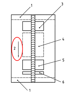
Figure 5 Location of test specimens in butt joints in plate

Location of test specimens in Figure 5 (welding direction top-bottom of page, see below).

Key

  1. Discard 25mm
  2. Welding Direction
  3. Area for:
    • 1 tensile test specimen;
    • bend test specimens.
  4. Area for:
    • impact and additional test specimens if required
  5. Area for:
    • 1 tensile test specimen;
    • bend test specimens.
  6. Area for:
    • 1 macro test specimen;
    • 1 hardness test specimen.

NOTE: not to scale.

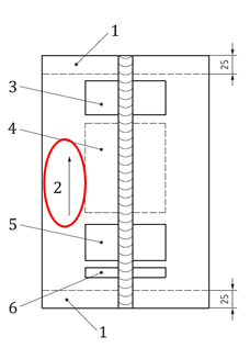
The welding direction is now from the bottom to the top of page, but the specimen location is the same. So, the location of test specimen with regard to the start and end of the weld has changed (see below).

Key

  1. Discard 25mm
  2. Welding Direction
  3. Area for:
    • 1 tensile test specimen;
    • bend test specimens.
  4. Area for:
    • impact and additional test specimens if required
  5. Area for:
    • 1 tensile test specimen;
    • bend test specimens.
  6. Area for:
    • 1 macro test specimen;
    • 1 hardness test specimen.

NOTE: not to scale.

  • Macro and hardness test specimen is now near the start of the weld. This was located near the end of the weld in the previous edition of ISO 15614-1.
  • Due to the heat building up during welding, hardness values may be higher at the start of the weld, compared to the end of the weld, for the same welding parameters. This effect has not been quantified.
  • So, the start of the weld represent a 'worst case' for hardness (ie highest hardness).
  • Procedure qualifications to the current ISO 15614-1 may result in higher hardness values.
  • Close monitoring of the heating cycle is recommended (preheat, heat input), especially when borderline hardness values are expected.
Figure 6 Location of test specimens in butt joints in pipe

No welding direction shown. So, specimen locations around the pipe circumference are the same, regardless of the welding progression (vertical-up or down)

Figure 6 split into two diagrams for vertical-up and vertical-down progressions, with specimens in different locations around the pipe circumference.

NOTE: for the vertical-down progression (right-hand side) the location of area 5 (start of weld, macro and hardness) in the diagram for the vertical-down progression seems to indicate that the start of weld should be at 3 o'clock position. Also, the location of area 1 (end of weld), seems to indicate that the weld ends at the 12 o'clock position. It is the opinion of the authors that this is an error and that a Key specific for the vertical-down progression diagram should be added.

  • Takes into account the effects of welding progression on the properties of different areas around the weld.
  • For example:
  • When welding in the vertical-up position, the worst case area for hardness (lowest heat input, highest hardness), is expected to be in the 6 o'clock position.
  • When welding in the vertical-down position, the worst case area for hardness, is expected to be in the 3 o'clock position.
  • Specimen shall be extracted from different locations, depending on the welding progression
Table 3 Permitted maximum hardness values

For material groups 4,5 (heat treated): Max 320 HV10

  • For material groups 4,5 (heat treated): Max 350 HV10.
  • New note c: for certain materials in Groups 4,5, higher values may be accepted, if specified before the welding procedure test.
  • Group 4 includes Low vanadium alloyed Cr-Mo-(Ni) steels with Mo ≤ 0,7 % and V ≤ 0,1 % (eg 0.5Mo steel)
  • Group 5 Cr-Mo steels free of vanadium with C ≤ 0,35 % (eg 1.25Cr -0.5Mo, 2.25Cr-1Mo)
  • The ISO committee agreed that the permitted hardness levels for Groups 4,5 in the previous edition of ISO 15614-1 were too stringent and the consensus was that Groups 4,5 (heat treated) may have a higher hardness level, without significantly increasing the risk of hydrogen cracking.
  • Footnote c was added because it was also considered that, for these materials, higher levels may be acceptable providing the hardness limit was specified before the welding procedure test. This may be useful, for example, when Group 4 and 5 materials are used for their mechanical strength, rather than their high temperature properties.
7.5 Acceptance levels

See clause 7.5

Table 4 added to clarify requirements

  • Acceptance criteria have been made clearer

Ranges of qualification

ISO 15614-1: 2004+A2:2012

ISO 15614-1:2017

Reason for change and main consequences

8.2 Manufacturer

Qualification valid for other workshops under the same technical and quality control

Technical and quality control not mentioned. Qualification valid "in workshops or sites when the manufacturer who performed the welding procedure test retains
complete responsibility for all welding"

  • The new wording clarifies that a company can apply another company's WPQR, provided that the companies that qualified the WPQR retains complete responsibility for all welding
  • For example: Company A, who carried out the procedure qualification, can pass the WPQR to Company B, provided that Company A retains complete responsibility for all welding
  • Company A would take a significant risk, as it would be responsible for welding carried out by a different company.
8.3.1 Parent material grouping

Refers to CR ISO 15608

  • Refers to ISO/TR 15608.
  • Where materials are assigned to groups by ISO/TR 20172, ISO/TR 20173 or ISO/TR 20174, those assignments shall be used.
  • Separate qualifications required for materials not covered by standards above
  • Rules to assign parent material grouping made clearer
  • ISO/TR 20172, ISO/TR 20173 or ISO/TR 20174 are very useful documents to assign groups to EN, American and Japanese materials
Table 5 Range of qualification for steel groups and subgroups

Table 3 has very few dissimilar combinations

Table 5 is much more comprehensive

Table 5 is now easier to use, especially for dissimilar metal welds

Table 5 Range of qualification for steel groups and subgroups

For Group 11 (mainly ASTM/ASME materials), note b applies, ie steels in the same sub-group and any lower sub-group within the same group lower sub-groups are qualified

For Group 11, note a applies, ie equal or lower specified minimum yield strength steels (independent of the material thickness) are qualified

  • Group 11 covers ASTM/ASME carbon steels, for which the specified maximum carbon content (up to 0.30%)  is typically greater than for 'EN or ISO steels'
  • Group 11 steels represent a worse case in terms of weldability (potentially higher carbon), compared to EN or ISO steels with the same or lower specified yield strength
  • The previous standard was considered unnecessarily restrictive, as Group 11 materials only qualified Group 11
  • Group 11 material now cover Group 1 with the same or lower specified minimum yield strength
Table 6 Range of qualification for nickel alloys groups and subgroups

Table 4 has very few dissimilar combinations

  • Table 6 is much more comprehensive
  • Dissimilar combinations for groups 8-4X and 11-4X introduced

Table 6 is now easier to use, especially for dissimilar metal welds

Table 7  Material and weld deposit thickness (butt welds)

Table 5 has the same ranges for weld deposit thickness material thickness

  • Separate qualification ranges for levels 1 and 2

Table 7 essentially similar to previous Table 5, except:

  • Deposited weld metal thickness (s) and material thickness (t) treated separately
  • Ranges for thickness of test piece have changed
    • No minimum thickness for deposit thickness
    • 0.5t – 2t for material thickness < 3
    • When s(test) > 20, new rules for s(max)
    • t(test) ranges 20-40, 40-100, 100-150, >150mm
    • S(max) = 1.33s(test) if t ≥ 150
  • Weld metal thickness and material thickness are treated separately to improve clarity
  • Users should be aware of the new thickness of test piece ranges and the new qualification ranges.
Table 8 Material and throat thickness for fillet welds

Table 6:

  • 3<t<30mm range = 0.5t(3 min) – 2t
  • t ≥ 30 : single run throat – no range (each throat depth to be qualified separately)

Table 8 :

  • 3<t<30mm range = 3-2t
  • Single run throat – range is 0.75a – 1.5a
  • As 3mm is the minimum material thickness then changed from 0.5t(3 min) – 2t to 3-2t
  • The standard committee considered that there should be a range of qualification for the throat thickness and not restricted, as previously, to the throat thickness used in the test piece.
Table 9 Pipe and branch connections diameter

Table 7 :

  • For D ≤ 25 range is 0.5D – 2D
  • For D > 25 range is ≥ 0.5D (25 min)

Range is ≥ 0.5D for all diameters

  • The committee considered the previous ranges to be too restrictive, so a range of ≥ 0.5D for all diameters was agreed.
8.4.1 Welding processes

For multi-run welds, no requirement to test weld metal deposited from each welding process

  • When the test piece is welded with more than one welding process;
    • The procedure is valid only for the sequence of processes used on the test piece.
    • Test specimens shall include deposited material from each welding process used.
  • Addition: "back run is permitted using one of the welding processes used in the qualification."
  • For multi-process welds, the test specimen must now include deposited metal from each welding process. This was not explicitly required in the previous edition.
  • For multi-process qualification (eg TIG+MMA), either of the processes can be used to deposit a backing run
8.4.2 Welding positions

8.4.2

The wording has been revised, the principles are the same apart from;

  • two test pieces are required except in the case of when a fixed pipe is used for the qualification.
  • More examples of high and low heat input positions provided in a NOTE
  • There has been much discussion on the clause and the wording was revised to make it clearer. The principles are largely the same but;
  • In case of fixed pipe, it is not necessary to weld two test pieces since, for example, the hardness can be taken from the overhead position (PE) and the impact from the horizontal (PC) position - see Fig 6
  • The UK specifically asked for the following to be included 'Vertical down welding (welding positions PG, PJ and J-L045) shall be qualified by a specific test' which was agreed.
  • The Note was added to help the user to understand which are the highest and lowest heat input positions.
  • The use of 'and' in the note, for example 'PF and PA' for high heat input position, may be misleading. Users may believe that two test pieces, one in PA and one in PF position, are required to test the high heat input. The intent of this note is that only one position per heat input level is required.
  • IMPORTANT: notes are included in standards to give examples and help the users. A note cannot include requirements. The positions specified in the note are for example only. The user may apply positions other than those indicated in the note.
8.4.3 Type of weld / joint

8.4.3

New clauses:

  • Weld made from both sides qualifies welds made from one side with backing
  • Build-up qualified by butt weld
  • Buttering shall be performed by a separate test piece in combination with the butt weld (to allow mechanical testing).

Modified clause (new text in Italic):

  • When impact or hardness requirements apply, it is not permitted to change a multi-run deposit into a single run deposit (or single run on each side) or vice versa for a given process
  • (i) and (k) were agreed by the committee and cover conditions that were not explicitly addressed in the previous edition
  •  (j): a change from single to multi-run, and vice-versa, is expected to affect hardness and toughness in the HAZ and weld metal. If hardness and toughness are not to be tested, this change should not apply.
  • (h) is not permitted when thermal gouging (arc air, plasma) is used to remove the weld root, because this is a thermal process and it affects the mechanical properties of the joint.
8.4.4 Filler materials
  • Covered by separate clauses 8.4.4 (designation) and 8.4.5 (make)
  • 8.4.5: filler metals restricted to the specific make for 'fluxed' processes 111 (MMA), 114 (self-shielded), 12 (SAW), 136 (FCAW inter gas) and 132 (FCAW active gas)
  • Covered by one clause (8.4.4)
  • Process 137 is replaced by process 132
  • Restrictions on filler metals for 'fluxed' processes (manual metal arc, SAW, FCAW) if impact testing is required at temperatures less than ‑20°C
  • Process 137 has been replaced by process 132 in the latest version of ISO 4063
  • The requirement for testing at -20°C is only mandatory if required by the Application Standard
8.4.7 Heat input (arc energy)

8.4.8:

  • heat input only to be recorded
  • ±25% qualified range, depending on testing requirements
  • Heat input calculation according to EN 1011-1

8.4.7:

  • User can use either heat input or arc energy for welding control, to be calculated in accordance with ISO/TR 18491
  • the calculation (either heat input or arc energy) shall be documented
  • ±25% qualified range stays the same (+25% when there impact requirements apply and -25% when hardness requirements apply)
  • For tack welding heat input need not be verified but adjustable parameters (amps/volts) should be checked
  • Reference to ISO/TR 18491 to take modern power sources into account
  • The traditional formula for heat input/arc energy in EN 1011-1 is inadequate when pulsed welding (eg P-GTAW or p-GMAW) or power sources with complex waveforms are used (eg Lincoln STT, Fronius CMT, ESAB Superpulse, Kemppi WISEROOT etc)
  • Using the traditional formula and average values for A and V has been proven to be inaccurate. Also, average A and V cannot be readily determined, when a complex waveform is applied.
  • ISO/TR User can report heat input or arc energy, to be calculated according to ISO/TR  18491
  •  provides separate rules to calculate heat input/arc energy for waveform controlled and non-waveform controlled processes
  • These are identical to the rules introduced in ASME IX since 2010
  • User should familiarise with ISO/TR 18491
8.4.8 Preheat temperature

8.4.9:
The minimum qualified preheat temperature is that recorded in the test (applied at the start of the test)

  • The preheat temperature can be reduced by no more than 50°C from the recorded preheat temperature on the WPQR otherwise requalification is required
  • A decrease in the preheat temperature is only permitted if ISO/TR 17671-1 2 is satisfied
  • Preheat temperature reduction similar to ASME IX, which permits a 55°C reduction .
  • A reduction of 50°C is permitted, rather than 55°C, to prevent level from being less stringent than ASME IX
  • It is permissible to reduce the preheat temperature from the recorded preheat temperature on the WPQR  but by no more than 50°C and only if ISO/TR 17671-2 is satisfied
  • This does not mean that preheat should be reduced for production welding. ISO/TR 17671-2 should be applied to determine the required level of preheat for production welding.
  • Also, a decrease in preheat temperature may not be permitted by the applicable construction code, if any.
8.4.9 Interpass temperature

8.4.10:
Upper limit for the interpass temperature (IP) is that recorded in test.

  • An increase in the maximum interpass temperature of more than 50°C shall require re-qualification
  • For Groups 8, 10, 41-48, there is no change, as the maximum interpass temperature (IP) is that recorded in the welding procedure test.
  • IP temperature increase similar to ASME IX, which permits a 55°C increase .
  • An increase of 50°C is permitted, rather than 55°C, to prevent level 2 from being less stringent than ASME IX
  • Increase not permitted for austenitic materials (groups 8, 41-48) and duplex stainless steels (group 10), as this may adversely affect properties such as toughness, phase balance and corrosion resistance
8.4.11 Heat treatment

8.4.12:
PWHT temperature range validated is the holding temperature recorded in the test ± 20°C

  • No changes from previous standard regarding temperature range validated and heating rates etc.
  • Introduction of four PWHT conditions which will require a separate procedure qualification
  • For material groups 1-7, 9-11 the following conditions apply:

- Stress relief (below lower transformation temperature),
- normalizing (above upper transformation temperature),
- normalising followed by Q&T,
- PWHT between lower and upper transformation temperatures.

  • PWHT temperature range validated is still the holding temperature recorded in the test ± 20°C
  • For all other groups PWHT shall be 'within a specified temperature range'.
  • Introduction of four groups of PWHT in line with ASME IX (see QW-407.1)
  • Major change is the introduction of four types of PWHT for ISO/TR 15608 material groups 1-7, 9-11
8.5.1 Submerged arc welding

8.5.1:

  • 8.5.1.1 Each process variant shall be qualified independently
  • 8.5.1.2 Range is limited to 'make and designation' of the flux
  • 8.5.1(a) Each process 12 variant (121 to 126) shall be qualified independently. The introduction of process variant such as multi-wire, addition of hot or cold wire, etc will require requalification
  • 8.5.1(b) Range is limited to the 'manufacturer, trade name and designation of the flux'
  • 8.5.1(c) New clause added to cover the use of re-crushed slag
  • Clause revised to improve clarity and address some frequently asked questions from users (eg on multi-wire, hot/cold wire etc)
  • Clause on re-crushed slag added in line with ASME IX (QW-404.36)
  • Limiting the range of qualification to the Trade Name used in the test is an additional restriction.
  • It should be noted, when using re-crushed slag a new batch or blend of crushed slag requires a new qualification test.
8.5.2.1 Gas-shielded metal arc welding (Shielding gases)

8.5.2:
Increase of 10% of CO2 content permitted for shielding gas

Maximum permissible deviation for the CO2 content has now been clarified as a 'relative deviation' of ±20% of CO2 from nominal composition

  • The previous wording (shall not exceed 10%) was unclear and numerous enquiries were being submitted
  • For example, if an increase of 10% is permitted, does a gas mixture 80% Ar 20% CO2 cover:
    • Up to 22% CO2, calculated as [20 + (10% of 20)]

or

    • Up to 30% CO2, calculated as (20%+10%)
  • According to ISO 15614-1:2017, for the example above, 'relative deviation of ±20%' means that a gas mixture 80% Ar 20% CO2 covers:
    • Minimum 16% CO2, calculated as [20 - (20% of 20)]
    • Maximum 24% CO2, calculated as [20 + (20% of 20)]
8.5.2.3 Gas-shielded metal arc welding (Transfer mode)

Spray or globular transfer modes qualify spray and globular

New clause on Transfer Mode

  • 8.5.2.3.1 The range of qualification for the various transfer modes including the pulsed mode eg qualification using spray, pulsed or globular qualifies spray, pulsed and globular

Range of qualification now covers the pulsed transfer mode and the newer waveform-controlled power sources

No reference to waveform controlled welding

New clauses on waveform controlled welding:

  • 8.5.2.3.2 Waveform-controlled welding: the power source manufacturer and waveform control mode are essential variables
  • 8.5.2.3.2 Welding with pulsed mode and without waveform-control: the power source manufacturer and other pertinent information shall be recorded, but a change does not require requalification
  • 8.5.2.3.2 Non waveform-control welding: the power source manufacturer shall be recorded, but a change does not require requalification

In practice:

  • If a power source with a complex waveform is used (eg Lincoln STT, Fronius CMT, ESAB Superpulse, Kemppi WISEROOT, EWM forceArc etc), the power source manufacturer and the waveform mode must be recorded in the WPQR and cannot be changed. For example, a qualification with Lincoln STT only covers Lincoln STT.
  • If 'conventional' pulsed welding is applied (no complex waveform), the power source manufacturer and the pulse parameters must be recorded in the WPQR. The power source manufacturer can be changed without requalification. NOTE: all other variables must be within the qualified range. So, one can change the power source BUT the pulsing parameters must be such that the qualified heat input limits are not exceeded.
  • For 'standard' welding (no complex waveform or pulsing): the power source manufacturer shall be recorded in the WPQR, but it can be changed without requalification.
8.5.3.1 TIG welding, shielding gases

8.5.3:
Shielding gas mixture limited to symbol of the gas or nominal composition

  • Shielding gas mixture limited to the nominal composition or symbol of the gas.
  • A relative deviation  of max ±10% from the nominal He content is permitted

See 8.5.2.1 for explanation of 'relative deviation'

8.5.4 Plasma arc welding

8.5.4:
No reference to joint type

A change in the type of joint preparation (groove) requires a re-qualification.

Clause on joint type added in line with ASME IX (QW-257 and QW-402.1)

8.5.6 Backing gas, all processes

8.5.3:

  • Backing gas rules apply to process 14 only
  • 8.5.3.2 A weld procedure test made without a backing gas qualifies a welding procedure with backing gas.

New clause on Backing Gases which covers the Material Groups

  • Backing gas rules apply to all processes
  • No backing gas qualifies backing with I and N1-N3 to ISO 14175 (not vice versa)
  • Main group to ISO 14175 covers all sub-groups within the same group
  • Material groups 1-6 – Gas groups I and N1, N2, N3 are interchangeable
  • Material groups 7 and 10 – Any change in backing gas classification requires requalification
  • Material groups 8, 41-48 – Gas groups I, N, R are interchangeable
  • Backing gas can be omitted when ≥5mm thick material backing is used

The rules on backing gas have been improved following feedback from users

Annex A

Not present

New Annex but not relevant for Level 2

Authors

Andy Brightmore (TWI) – Software Business Development ( http://www.twisoftware.com/ ).

Marcello Consonni (TWI) - Member of ISO subcommittee ISO /TC 44/SC 10 'Quality management in the field of welding', UK national committee WEE/36 'Qualification of welding personnel and welding procedures' and contributing member of ASME BPVC Section IX committee.

Professor Bill Lucas – UK delegate on ISO subcommittee ISO /TC 44/SC 10 'Quality management in the field of welding', national committee WEE/36 'Qualification of welding personnel and welding procedures'.

Last reviewed: December 2017

Posted by: yongjacksitse0193725.blogspot.com

Source: https://www.twi-global.com/technical-knowledge/faqs/faq-whats-new-in-iso-15614-1-2017
Post a Comment for "iso 15614 1 pdf free download"